AI
Techniques for Conceptual Design
Date Rentema and Frederik W. Jansen
Conceptual design is the first phase of the design process. Its role is to come up with a first proposal that satisfies the functional requirements. Conceptual design is difficult in particular for complex objects such as aircraft, ships, and industrial appliances. The list of requirement is generally quite long and it often takes a full detailed design to assess whether the proposed solution satisfies the functional requirements, only to learn in the end that it does not. So we need a system that can quickly generate a proposed solution and that can evaluate whether it satisfies the posed requirements without extensive detailing effort.
In this work, we propose a design methodology for conceptual design, using several AI techniques, which in combination support the total design cycle of proposing and evaluating solutions.
We will first discuss conceptual design and how AI techniques can be used to implement the required qualitative kind of reasoning needed for suggesting and analysing design concepts. Then we describe the application of these techniques within the AIDA system (AI supported Design of Aircraft) and show how this system can be used for the design of aircraft. A more elaborate version of the case can be found in [Rentema 2004].
Conceptual
Design
Design is an activity that generates a 'materialised' solution for a 'functional' problem, i.e. it proposes a system or 'structure' that shows some 'behaviour' that satisfies the 'functional' demands. However, there is no direct reasoning possible from functions to behaviour and structure, i.e. a logical, straightforward deduction of the structure from the function is not possible. It is even feasible that more than one structure is capable of realising the demanded functions, or none at all. Hence, designing is a non-deterministic process.
Designing has more challenging features. Typically, it is often an 'ill-defined' process, meaning that the functional requirements may change during the process, for example when they appear to be too conflicting. Also time and resources may be limited, and we may have to decide in a situation of uncertainty. Another challenge is to define the optimality criteria based on the diversity of design specifications, in order to generate an optimal design or select the best feasible design.
Because straightforward reasoning is not feasible, a
'generate-and-test' strategy is often applied. This strategy leads to a number
of iterations through the design cycle which is visualized in Figure 1.
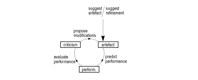
Figure 1. The Design cycle
Using his experience, the designer first suggests a solution, then the performances are predicted/estimated. This may be done with some formalized knowledge such as physics, statistical data or empirical 'rules-of-thumb'. A full analysis is often not possible due to lack of a detailed description. After the performances are evaluated with respect to the requirements, then modifications may be proposed to remedy the shortcomings, and the cycle starts over again. When the solution is deemed to be good enough, the design may enter the next stage of refinement. This means that the artefact will be described more completely by adding details, for example by focusing on one of the components.
An often applied strategy to avoid exhaustive generate-and-test search is the 'divide-and-conquer' method. The problem is decomposed into several sub-problems that are easier to solve and the different sub-solutions are then combined into one integrated solution. An example of such a decomposition strategy is the 'function-means' method. Requirements are recursively decomposed until a solution can be provided and the part-solutions are then successively combined. This decomposition strategy does not solve the design problem itself but transposes it to the 'integration' activity; however, the initial decomposition and analysis may provide some useful clues for the integration phase. The decomposition-integration cycle can be repeated for different levels of detail, or different functional decompositions.
The integration step can be avoided when an existing solution is taken as a starting point. The chosen solution, which partly satisfies the new functional requirements, is then refined via a 'reuse-and-adapt' or 'diagnosis-and-repair' cycle. The solution is analysed and modifications are proposed that relieve some of its weaknesses.
This approach is better suited for so-called 'routine design' problems than for 'creative' designs where new principles are applied in a new context. Most designs fall in between routine design and creative design: a new design is often a new composition of existing components. According to [Mittal, 1989] this type of design can be classified as 'configuration design'. Typically large-scale design problems such as design of aircraft, buildings, ships and industrial appliances fall into this category: certain aspects of a new design may be 'innovative' but in most cases there will be quite some similarity with earlier designs.
Although the reuse of existing components greatly simplifies the design process, the number of possible combinations is still far too large to be fully elaborated. Hence a good initial choice is very important. In the next section we will review to what extent AI techniques can be used to cope with these issues.
2. AI and design
Artificial Intelligence (AI) is concerned with the application of knowledge. Within AI, three main directions of reasoning can be distinguished: reasoning by logic, reasoning by learning, and reasoning by analogy. Expert systems apply rule-based reasoning (RBR) technique, a form of reasoning by logic. An expert system is useful when the domain knowledge can be formalised into simple rules, such as mathematical problems, and when common sense does not play an important role. Unfortunately, design can not be formalized this way.
Reasoning by learning can be implemented with Artificial Neural Networks (ANN). An ANN consists of a network of nodes (processing elements) connected via adjustable weights (connections). By training the network with a large set of input-output pairs, the system learns the functional relation between the input and the output space. This type of generalized learning can not be applied to the design problem because the solution space is sparse and discontinuous.
The third form of reasoning, reasoning by analogy, is best exemplified by Cased-Based Reasoning (CBR). Cases are stored in a case-base to create a reservoir of problem-solution combinations. When a new problem is presented, CBR searches for cases with similar problem descriptions. Although the retrieved case usually does not completely fit the new problem, the retrieved solution may be a good starting point for further adaptation and optimization. The difference with the other AI methodologies is that CBR does not use generalized domain knowledge but knowledge which is locally valid: the implicit knowledge within a case which relates a problem with a solution only holds for that particular case. See Figure 2.
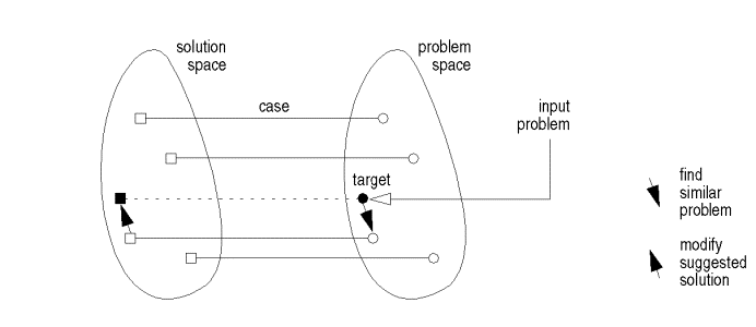
Figure 2. Principles of problem-solving with Case-Based Reasoning (from [Leake,1996])
Considering the characteristics of conceptual design, reasoning by analogy seems to be a helpful method to assist the suggestion of a concept. Because CBR applies implicit knowledge, this paradigm offers interesting possibilities to overcome the lack of (quantitative) knowledge at this design phase. CBR in design, however, differs from other CBR applications where the number of cases is generally quite large but each individual case is relatively simple. In design the examples are few but often complex and may cover a large diversity of functions. Hence, to be able to use CBR properly, the information about the design cases will have to be encoded in a flexible way.
A useful representation scheme for design cases is the triad Function-Behaviour-Structure [Gero, 1992]. Structure represents the materialized version of the design: the geometry, the components and the assembly. Function represents the performances of the functional aspects of the model. Behaviour describes more explicitly how the structure is able to accomplish the functions; i.e. the mechanism by which the (functional) problem is solved. The behaviour component is very much dependent on the structure. Given two different design configurations, there may be a completely different set of behaviour data to evaluate each of them.
Furthermore we should be aware that, in addition to functional requirements, the list of specifications may also contain explicit requirements for the behaviour and structure of the design (e.g. the use of certain components). Some functionality may therefore be the result of behavioral and structural choices, and not explicitly be prescribed by the list of functional requirements.
For the evaluation of the structure via behaviour and function, explicit (physical and mechanical) domain knowledge may be applied. Because of its logical character, the RBR technique seems suitable for controlling this knowledge. Compared with the conventional techniques implemented in a static manner in existing computer support tools, rule-based techniques offer a more flexible use of domain knowledge. By logical reasoning, a correct chaining of calculation methods can be found to determine a proper evaluation sequence. Also the transparency of the applied knowledge will be improved. Instead of performing complicated calculations within a module, RBR can be used to split up these calculations into basic functions and connect them on-line by logical reasoning (and helped by interactive specification of the user).
Strongly associated with the evaluation functions are constraints and relations imposed on the (standard) components of the structure. These constraints keep the structure functionally consistent, encode some form of parametrization of the structure, and/or be part of the interface specification between components. These constraints are not directly used to evaluate the design but to model the design and put some intelligence into the configuration and adaptation process.
The next section will describe how these techniques can be applied for conceptual design of aircraft. A system set-up is presented based on the use of case-based reasoning to propose design concepts, rule-based-techniques for the functional evaluation, and constraint-based geometric modeling for the geometrical evaluation of these concepts.
3. The AIDA system
The AIDA system (AI-supported Design of Aircraft) is built of three modules and a central interface; see Figure 3:
· Case-based
reasoning (CBR) module
In this module case-based reasoning techniques are implemented to generate an
acceptable initial concept which can be modified in the Functional module.
· Functional
module
In this module rule-based reasoning techniques are implemented to perform
sensitivity studies on the primary parameters of the concept. With these
studies a feasible concept is designed.
· Geometrical
module
This module automatically models and visualizes the concept. It uses
feature-based and constraint-based modeling techniques.
· Central
user interface (CUI)
This module handles the communication between the other three modules.
For each module existing tools have been used. The following paragraphs describe the separate modules. We will illustrate their function with a case taken from aircraft design. It is based on a conceptual design study for a 70 passenger regional airliner [Franssen, 1996].
3.1 Case-based reasoning module
As suggested by its name, the Case-based reasoning (CBR) module applies case-based reasoning techniques to generate an acceptable concept from the design specifications. These techniques enable the use of design experience which is implicitly available in existing cases. Also, case-based reasoning is an approach to learning, since the result of succeeded design sessions can be added to the case-base, making it available for future design problems.
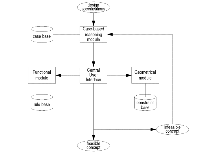
Figure 3. Modular set-up of the AIDA-tool.
A complete case-based reasoning process can be considered as a cycle of four sequential steps; see [Aamodt, 1994] and Figure 4:
· retrieval: find cases in the case-base which resembles the problem description;
· reuse: copy case-data or combine data of more cases;
· revision: evaluate the proposed solution; and
· retaining: put successful 'learned case' in the case-base.
The problem description defines the 'new case'. In the retrieval step the case-base is searched for cases with data matching the 'new case'. The cases with most similar data are retrieved. In this step the matching process is most critical.
In the reuse step data is copied from a 'retrieved case'. Usual the 'retrieved case' does not completely match the 'new case', i.e. the best matching case does not completely solve the problem. In that situation the data of other 'retrieved cases' can be combined. In other words, the best matching case is changed/adapted with data of other selected cases. This adaptation process requires domain knowledge and is very complex.
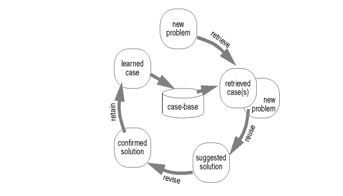 The
result of the reuse step, the 'solved case', is a suggested solution to the
problem. It is evaluated and repaired when necessary in the revise step. The
evaluation process is often performed by numerical tools. This process also
requires domain knowledge, as does the repair process. The result is a
'tested/repaired case', or a confirmed solution to the problem.
The
result of the reuse step, the 'solved case', is a suggested solution to the
problem. It is evaluated and repaired when necessary in the revise step. The
evaluation process is often performed by numerical tools. This process also
requires domain knowledge, as does the repair process. The result is a
'tested/repaired case', or a confirmed solution to the problem.
Figure 4. The CBR cycle (adapted from [Aamodt, 1994]).
The learning aspect is implemented by adding information about the confirmed solution to the case-base. The retain step handles the transformation from the 'tested/repaired case' into the 'learned case'.
In AIDA, only the retrieve, the reuse and the retain steps are implemented in the Case-based reasoning module. The evaluation in the revise step is taken care of by the Functional module, using rule-based reasoning techniques; see next paragraph. The CBR module has been developed in EADOCS [Netten, 1997, 1998], a design system for composite sandwich panels. In this CBR module the retrieve step, as well as the reuse and the retain steps have been implemented (see section 3); the revise step has been implemented in another module.
In aircraft design, the cases contain data about their function or performances, such as the range and speed, and data about their structure or physics, such as the weights and sizes. Also data which numerically expresses the quality of the aircraft is added, such as the wing-loading and maximum lift-coefficient; according to [Rosenman, 1994] these can be considered as behavioural data.
The CBR module consists of two parts. The first part generates an indexing network. This network provides an index to the cases by the use of parameter domains. These parameter domains allow qualitative labelling of the continuous parameter values, such as 'small and 'moderate' etc., to enable a kind of qualitative matching. The network is created off-line to improve the efficiency.
 The
second part uses the network to search for cases similar to the specified
'target set'. This is done on-line. For each part of the target set the
matching results are shown, and the cases are ranked accordingly. The
importance of each part of the target set is given by priority-values.
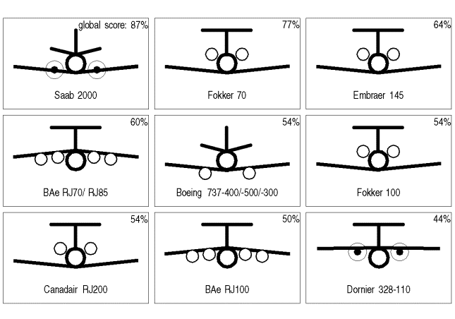
Figure 5 shows a list of best-matching aircraft configurations.
The
second part uses the network to search for cases similar to the specified
'target set'. This is done on-line. For each part of the target set the
matching results are shown, and the cases are ranked accordingly. The
importance of each part of the target set is given by priority-values.
Figure 5 shows a list of best-matching aircraft configurations.
Figure
5. An example of best-matching aircraft configurations.
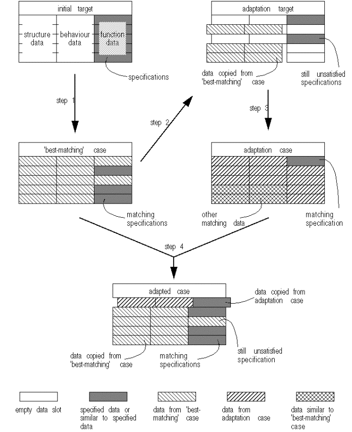
The strategy used for the CBR module is to first retrieve a 'best-matching' case, and then to reuse parts of other cases for adaptations. The adaptation process, however, disrupts the link between the functional and the structural data. Therefore the adapted case is probably not valid anymore. The adapted case should be evaluated before other adaptations can be usefully applied.
To adapt the case properly is difficult, due to the many interactions between the functional data and the structural data. Therefore a strategy is followed which should lead to as little adaptations as possible. A secondary target set is defined, consisting of the rest of the specifications which the 'best-matching' case does not satisfy, together with the most important structural and behavioural data of the 'best-matching' case. The result of the new matching process will give cases which resemble the structure of the 'best-matching' case, and which (partly) satisfy the functional requirements that the best-matching case does not meet. In Figure 6 this strategy is summarized.
Domain knowledge is used to support the adaptation process. Expert rules have been collected which may help with focusing on the relevant data. For instance, when the 'best-matching' case does not reach the specified speed (function), the designer should focus on the thickness of the wing and its sweepback angle (structure).
 Figure
6. Case adaptation strategy.
Figure
6. Case adaptation strategy.
The CBR module delivers a complete case, which may be inconsistent due to the adaptations. The complete structural data set is required by the Geometrical module in order to make a solid model of the concept. Some structural and some behavioural data is required by the Functional module when generating a relational network. They provide proper initial estimations which can be evaluated and modified.
3.2 Functional module
The Functional module supports the execution of parameter studies. These are used to evaluate and modify the adapted case as produced by the CBR module. The result is a feasible concept, according to the available knowledge. This knowledge is represented by numerical relations which express the heuristics such as collected in books on aircraft design [Roskam, 1987] [Torenbeek, 1982].
In the Functional module rule-based reasoning techniques are applied to generate a network of numerical relations. The rules implement heuristic knowledge and simplified physics in an algebraic format. The network of these rules links functional parameters (from the specifications) to structural parameters (from the designed object). With this network sensitivity studies can be performed to estimate the structural parameter values. This reasoning technique offers the flexibility to easily generate a different network for a different set of specifications.
The Functional module is implemented in Quaestor [van Hees, 1997], an expert governed system for the assembly, execution and maintenance of parametric design models. This tool has been developed to support ship design in the early phases of design by improving access to and control over design related knowledge.
Before Quaestor can be used, the rule-base has to be built. The rules represent numerical relations in an algebraic format. To each rule, conditions can be added to incorporate its limited validity. This is often the case with the heuristics and simplified physics. Within Quaestor the conditions are called 'constraints'. The third type of element within Quaestor is the parameter. The rule-base is built by one or more experts, which do not have to be the same persons as the designer which uses the Functional module.
The designer starts a Quaestor session selecting the parameters to be calculated, for example the desired functional performance characteristics. These are called the goal parameters. The inference engine of Quaestor searches the rule-base for relations which do calculate this goal parameter. The designer selects one of the suggested relations. Usually the new relation introduces other, unknown parameters. The designer can make the unknown independent or dependent. The parameter becomes independent when it gets a value, for instance a value generated by the CBR module. When the parameter is a function of other parameters then the parameter is set to be dependent and it becomes a new goal parameter for which other relations have to be found. So, a backward chaining strategy is applied.
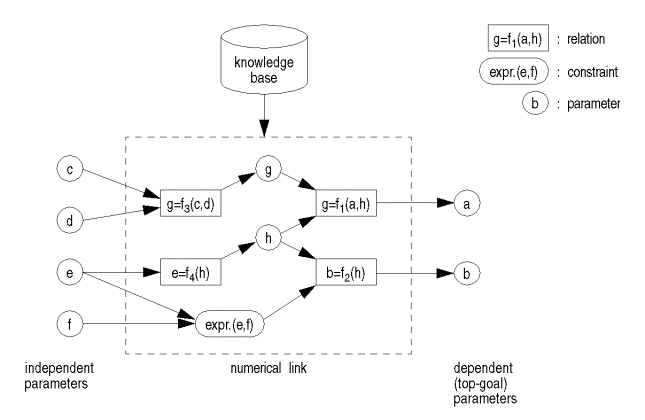
The creation of the relational network is finished when no goal parameters are left. When the network is completed, the number of dependent parameters is equal to the number of relations. Quaestor uses Newton-Raphson and simplex methods to solve the set of relations, and calculate the goal parameters. Figure 7 shows a simple numerical link.
 It
is important to notice that Quaestor also searches for relations with the goal
parameter on the right-hand side of the algebraic notation. This makes Quaestor
very flexible. Instead of an algebraic relation also an external application
can be part of the network. This possibility makes the module even more
powerful. However, the input and output parameters of these applications have
to be known in advance.
It
is important to notice that Quaestor also searches for relations with the goal
parameter on the right-hand side of the algebraic notation. This makes Quaestor
very flexible. Instead of an algebraic relation also an external application
can be part of the network. This possibility makes the module even more
powerful. However, the input and output parameters of these applications have
to be known in advance.
Figure 7. A Quaestor template, linking independent with dependent parameters.
To perform parameter studies, independent parameters can be
given an array of values. The resulting arrays of the goal parameters can be
saved in an file, to be viewed graphically by the Central User Interface (CUI).
3.3 Geometrical module
The Geometrical module models and visualizes the suggested aircraft concept. This gives the designer a visual feedback of the concept. The module can also deduce some geometrical properties, such as volumes and areas.
The module is implemented in Pro/Engineer [PTC, 1999], a commercial feature based solid modeller. In this modeller the solids are constructed with engineering features, such as holes, protrusions, rounds etc. Features can be combined into parts, which can be combined into assemblies. The features are defined and located by parameters and by constraints between parameters and features. With these relations Pro/Engineer is able to preserve the consistency of the model when parameter values are changed.
Pro/Engineer can handle the variation of continuous parameters very well. However, to change the definition of features, parts and assemblies requires knowledge of the package, which is not the intention of the Geometrical modeller. Therefore the aircraft concept model is constructed with pre-defined parts, such as the fuselage, the wing, the engines, the horizontal and the vertical tail-surfaces. The geometrical constraints between these parts keep them properly located.
It is possible to visualize different types of these pre-defined parts, for example turbofan and turboprop engines. Both types are pre-defined, and the parameter which defines the type of engine will automatically suppress the other types. This way the variation of the discrete parameters is managed.
This strategy of using standard aircraft parts is practicable because it is known which configuration elements are in the case-base. Figure 8 shows the hierarchical structure of the aircraft model.
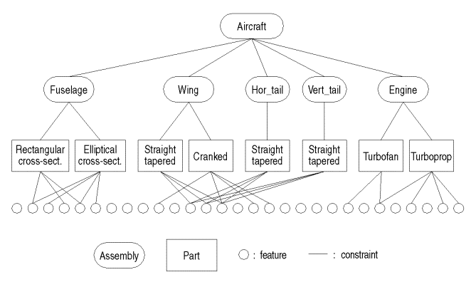
Figure 8. The hierarchical structure of the aircraft.
The Geometrical module is able to show a three-dimensional view as well as three side-views of the model. Figure 9 gives an example of a three-dimensional view. The model can also saved in several graphical formats, for use of other computer programs.
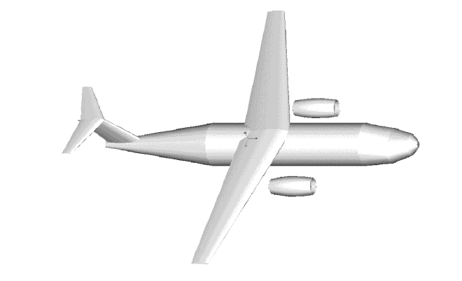
Figure 9. A shaded, 3-dimensional view of a concept
design.
3.4 Central user interface
The Central User Interface (CUI) handles the interaction between the other three modules and the designer.
It reads the data generated by the CBR module, of the adapted case, filters it and directs the required data to the Geometrical module. The CUI is also able to present the results of the sensitivity studies, performed by the Functional module, in a graphical format. See Figure 10.
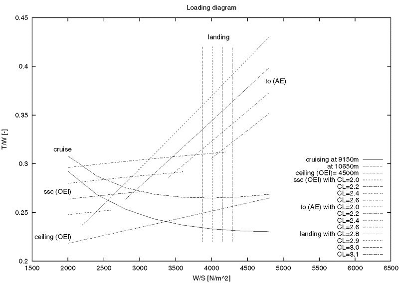 Figure
10. Sensitivity studies of some behaviour parameters in aircraft conceptual
design.
Figure
10. Sensitivity studies of some behaviour parameters in aircraft conceptual
design.
4. Conclusions
We have analysed the conceptual design process, and suggested a design cycle that uses CBR-techniques to propose and adapt initial concepts, RBR-techniques to analyse and evaluate the concept, and geometric modeling techniques that model the concept automatically. These three techniques are implemented in three independent modules, with a central user interface to connect the modules.
The system has been evaluated for the conceptual design of aircraft. This application allows the decomposition of the design product into basic components. The current approach therefore relies heavily on the decomposition of the design product into basic components. For a more general approach without the basic components the case representation will need to be more comprehensive.
Another aspect of further research will be the implementation of the separate modules into one integrated framework.
Acknowledgements
The AIDA project was initiated by dr. Rob Vingerhoeds and prof.dr. Henk Koppelaar of the Knowledge-based System group and prof.ir. Egbert Torenbeek of the Aircraft Design group.
References
Aamodt, A., Plaza, E., Case-based reasoning: foundational issues, methodological variations, and system approaches, in: AICOM, Vol. 7, Nr. 1, March 1994.
Franssen, S.H.J.A., Conceptual design of a 70 passenger regional airliner propelled by fuel-efficient turbo fan engines, memorandum M-725 of the Faculty of Aerospace Engineering, Delft University of Technology, The Netherlands, October 1996.
Gero, J.S., Tham, K.W., Lee, H.S., Behaviour: a link between function and structure in design, in: Brown, D.C., Waldron, M., Yoshikawa, H. (eds), Intelligent computer aided design, Elsevier Science Publishers B.V., The Netherlands, 1992, pp. 193-221.
Hees, M van, Quaestor: expert governed parametric model assembling, PhD thesis, Delft University of Technology, The Netherlands, 1997.
Leake, D.B., Case-Based Reasoning: experiences, lessons, and future directions, AAAI Press, 1996.
Mittal, S., Frayman, Towards a generic model of configuration tasks, Proc. 11th IJCAI, Morgan Kaufman, 1395 - 1401.
Netten, B.D., Knowledge based conceptual design; an application to fiber reinforced composite sandwich panels, PhD thesis, Delft University of Technology, The Netherlands, 1997.
Netten, B.D., A hybrid reasoning system for conceptual design, in: AAAI-98 Workshop Case-Based Reasoning Integrations, Madison, Wisconsin, July 27 1998.
PTC, Pro/Engineer manuals, release 2000i, Parametric Technology Corporation, USA, 1999.
Rentema D.W.E., Jansen F.W., Netten B.D., Vingerhoeds R.A., An AI-based support tool for the conceptual design of aircraft, in: Computer Aided Conceptual Design (CACD'97); 1997 Lancaster International Workshop on Engineering Design, Cumbria, England, April 1997.
Rentema D.W.E., Jansen F.W., Torenbeek, E., The application of AI and geometric modelling techniques in conceptual aircraft design, in: 7th AIAA/USAF/NASA/ISSMO Symposium on Multidisciplinary Analysis and Optimization, St.Louis, Missouri, USA, September 1998.
Rentema, D.W.E., AIDA: Artificial Intelligence Supported Conceptual Design of Aircraft, PhD thesis, Delft University of Technology, Nov. 2004.
Rosenman, M.A, Gero, J.S., The what, the how, and the why in design, in: Applied Artificial Intelligence, Vol.8, 1994.
Roskam, J., Airplane design; Parts I-VIII, Roskam Aviation and Engineering Corporation, Ottawa, Kansas, USA, 1987-1990.
Torenbeek, E., Synthesis of subsonic airplane design, Kluwer Academic Publishers, Dordrecht, The Netherlands, 1982.